1. Why do I need to know?
You need to understand the principles of CT/VT valves because they are important in larger heating systems as they are the method of providing the right temperature hot water from boiler(s) to the various equipment that needs it, such as hot water cylinders (also called calorifiers) and heating circuits (“Demand”). The boiler can only output hot water on the primary circuit at one specific temperature at a particular point in time; and this will be the higher of the temperatures required to satisfy Demand. CT/VT valves are a method of reducing the boiler flow temperature for heating circuits that need to run at a lower temperature. They also help in reducing energy costs as modern CT/VT valves can be controlled via a BMS system to maximise energy saving. Not all BMS systems can do this, so choose carefully.
2. How it works?
2.1. Constant Temperature (“CT”) and Variable Temperature (“VT”) valves are used to maintain a set-point in the primary circuit of a hot water based heating system. In this type of heating system the temperature of the water in the boiler flow pipe may vary wildly due to demands for heat from other heating circuits, such as hot water cylinders or other central heating pipe circuits.

Fig 1
2.2. Fig 1 above is a schematic of a boiler and the associated pipework. Here, the boiler is set to provide a flow temperature of 75°C so that a hot water cylinder (not shown in Fig 1) can also be quickly heated. The problem arises in that whilst the pipe flow temperature is fine when quickly heating the hot water cylinder, it’s a too hot for the central heating system; which in this case comprises fan assisted radiators.
2.3. The effect is that the 75°C Primary Circuit will pump out hot air at approximately 75°C one moment, and then when the room is up to temperature, this supply of hot air will stop. Then when the room temperature drops below its set-point another blast of 75°C air will come from the fan assisted radiator. This effect causes nausea for the people within the room.
2.4. To over come this problem, a slipper valve is installed on the boiler flow, just after the central heating pump. Opening the valve will cause some of the flow into the heating circuit whilst the rest returns to the boiler (this is called a “bypass”).
2.5. CT and VT valves comprise a valve body and an Actuator head that is fitted to the valve body to replace the red lever shown in illustrations Fig 2 and Fig 3 below. HeatingSave is used to control the Actuator.
Fig 2 Fig 3
2.6. Fig 4, Fig 5 and Fig 6 show the CT/VT valve body view from the bypass valve orifice. As can be seen, the position of the red lever controls the opening in the internal brass slipper valve, which determines the amount of hot water that is passed to the CT/VT circuit, or, returned to the boiler via the bypass circuit.
Fig 4 Fig 5
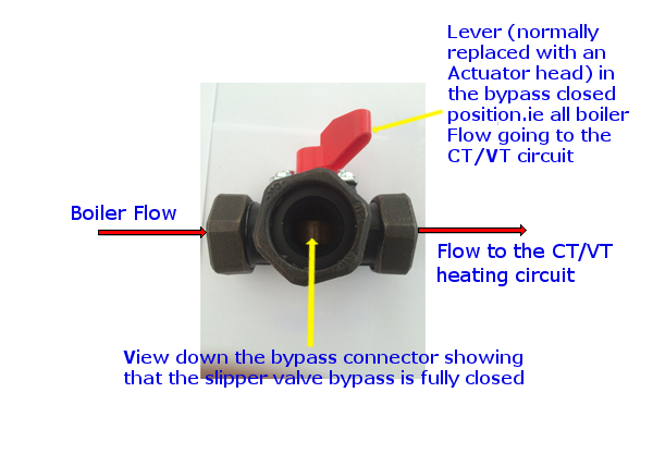
Fig 6
3. What’s the difference between a CT valve and a VT valve?
3.1. The important point here is that CT and VT valves are the same physical device. The only difference is the way in which they are logically used (i.e. in the HeatingSave software). In CT mode HeatingSave ties to maintain a Constant output temperature for the time that a particular heating hydraulic circuit is in operation. In VT mode HeatingSave maintains different output temperatures for the time that a particular heating hydraulic circuit is in operation, depending upon a Heating Pattern set-point. Historically, CT/VT valves were often physically different devices because they came with their own (often mechanical) controller.
3.2. As shown in Fig 2 to Fig 6, each CT/VT valve has a valve body which is essentially a 3 port valve on the boiler flow. The primary circuit water is proportionally diverted, via a slipper valve, either to the heating circuit where the CT/VT temperature is trying to be maintained, or to “bypass” which sends it back to the boiler Return.
3.3. Mounted on the valve body is an Actuator (in replacement of the red lever shown in Fig 2). This Actuator, using an electric motor, moves the slipper valve in one direction or the other (i.e. more “open” or more “closed”). This Actuator is in turn controlled by HeatingSave. Actuators have typically two methods by which HeatingSave can control them.
3.3.1. About 70% of the CT/VT Actuators installed in heating systems have two live 240VAC and a neutral wire. Here, if power is applied to one of the “live” wires the motor will move in one direction and if power is then removed from this “live” and put on the other “live”, then the motor will move in the other direction. So, you can see that with two 204VAC relay outputs, HeatingSave can control the CT/VT valve. The HeatingSave software does the rest.
3.3.2. The other 30% of CT/VT valves provide proportional control to the CT/VT Actuators via a 0-10 VDC input. Here, HeatingSave varies the 0-10VDC DAC output (there are two DAC’s on each T3520 and none on a T3516) to open and close the slipper valve. Although this can vary valve-to-valve, a 5 VDC supply would hold the mid position, 0 VDC would hold the valve fully open and 10 VDC would hold the valve fully closed (or vice versa?)
3.3.3. Fig 7 shows a
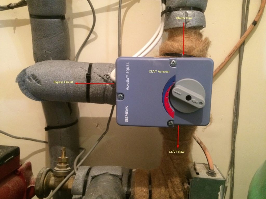
Fig 7
4. Show me real-world examples
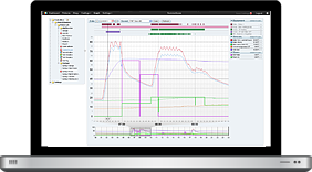
4.1. Fig 8 shows a live system where HeatingSave is controlling a CT/VT valve in an attempt to maintain a constant 50°C on the CT/VT flow. It has to do this whilst competing for other demands that can occur impromptu. This particular system is difficult but HeatingSave generally manages the situation.

Fig 8
4.2. Fig 9 show another live system, where this time the competing demands are less. Here, it can be seen that HeatingSave manages the cycling of the CT circuit about the set-point better. Note that in this case the VT set-point is changed between 06:25 and 06:35. See how HeatingSave tries to compensate and then restores the 50°C heating temperature for the 2nd CT.

Fig 9
4.3. As far as we are aware, HeatingSave is the only BMS system that off-the-shelf shows this level of detail so that its possible to see how well the HVAC system is working.